Construction & Engineering Awards 2024
Журнал BUILD объявляет победителей конкурса Construction and Engineering Awards 2024 От противопожарной защиты до продуктов UHPC, сантехники…
Журнал BUILD объявляет победителей конкурса Construction and Engineering Awards 2024 От противопожарной защиты до продуктов UHPC, сантехники…
NEWSLETTER May 2020 Thank you to all of our F.A.S.T. assemblers out there for what you do,…
Company “Systems of Controls – CONSYS” is able to provide you with Controls for mechanical and automatic gearshift boxes of any configuration. At the present time there are many options for transmissions, but ordinary mechanical (manual) is still quite popular.
The usual mechanism of transmission control uses a system of levers, but control cables mechanism is more modern (Fig.1.), used in buses, where the gearbox and the engine located in the rear or on the truck where the driver’s cab tilts for access to the engine and gearbox.
This mechanism consists of master unit (Fig.2.), remote control cables (selection and switch) and a variety of fittings (joints) for cables (Fig.3.) mounting. Master support may also be called a side scene or selector and be horizontal, vertical and inclined. Master unit (selector) can be horizontal, vertical and inclined.
Generally, control is carried out by hand. Driver sets lever of control mechanism in the position corresponding to a specific transmission gear. In a neutral (intermediate) position (no gear engaged) lever has sufficient ability to move laterally. In this case is a choice – which of the gear switch. Gear is turned on by moving the lever forward or backward.
It should be noted that the selection and switch cables structurally different from each other and are not interchangeable.
Fig.1. Gearshift cable drive
Gearshift cable drive (Fig.1.) consists of master unit (switching mechanism) – 1 and control cables (selection – 2 и switch – 3). Depending on the design of the gearshift, actuator may also include translators and rods – 6. Availability of different methods of fastening of a cable – 8 as well as a wide variety of fittings – 9 can be used for various designs transmissions.
On request, cable drive can be additionally equipped with a parking brake cable.
Fig.2. Overall construction of master unit
Control cable (Fig.3.) designed for mechanical transmission of the energy of motion (shear forces). Directly cable core passes efforts and conduit serves as a core guide and his defense. Depending on the required effort and cable travel using “CONSYS” catalogue you can select cable corresponding series (3, 4, 6, 8) as well as selected other necessary characteristics (dimensional, temperature, etc.). The standard for each cable are high-quality seals. They prevent the ingress of moisture and contaminants in cable, which improves performance and efficiency of the cable in all temperature conditions.
Bearings for rod and sleeve are made of a special polymer and are used to seal and prevent contact between rod and sleeve.
Fig.3. Overall construction of control cable
As stated above, master units design may be different.
Following are horizontal master unit (Fig.4a.); vertical master unit (Fig.4b.).
Fig.4a. Master Unit (horizontal)
Fig.4b. Master Unit (vertical)
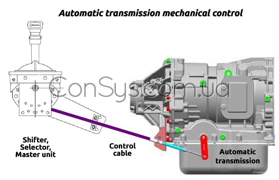
Automatic transmission control carried out by the shifter (selector, master unit) and remote control cable. With shifter selects the desired mode of operation for automatic transmission. In this case the movement of shifter knob to the desired position via remote control cable changes the position of the appropriate lever on the automatic transmission. The advantage of this control system is the ability to place the shifter in site required by driver or operator and by control cable lay necessary cable route to the automatic transmission, in whatever part of the vehicle she was.
